
DC Inverter Liquid Cooling Unit(LCI) for Container Energy Storage
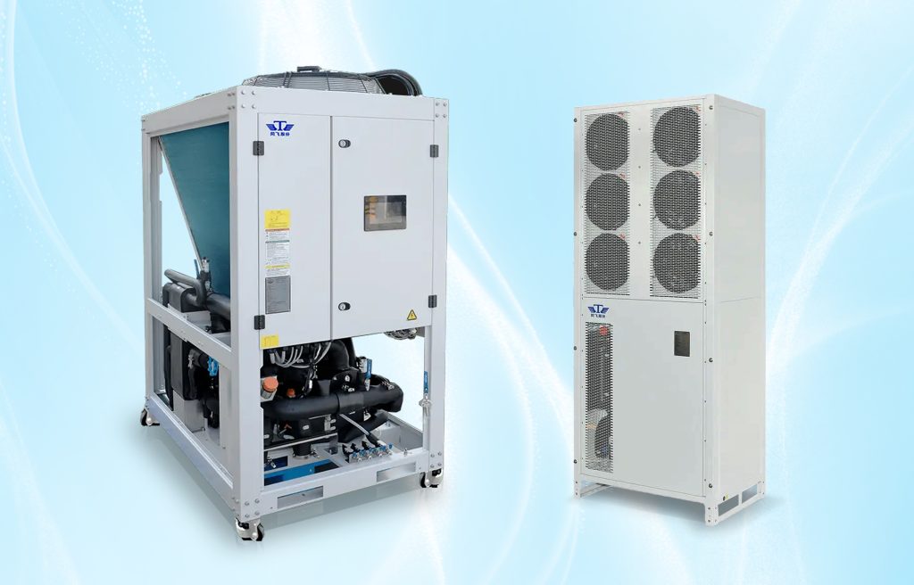
We offer OEM, ODM, CKD, and SKD services worldwide.
Application industry
New energy storage industry
Applications
It is suitable for large-scale energy storage cabinets, and the storage power of energy storage cabinets is about 3.5MW/h.
Features
- The protection level of the whole unit is IP54, and the electrical box is IP56, which has a high protection level and high reliability;
- The control system adopts a capacitive touch screen Chinese and English bilingual conversion computer controller, CPU automatic control, which can realize man-machine dialogue, simple and intuitive operation;
- Water temperature control accuracy±1°C; It has the function of automatic fault diagnosis, which directly displays the fault point on the screen and prompts the user to deal with it quickly;
- Provide RS485 and CAN communication interfaces, which can realize the communication function with the host;
- The unit can work stably in the ambient temperature range of -30°C-55°C, and provide stable and reliable temperature control ability for the battery energy storage system;
- The water inlet and outlet are φ50.8 chucks, which can realize the rapid installation of the waterway system;
- Adopt a certain one-transformer and double compressor system to realize intelligent adjustment of unit energy consumption, with a large adjustment range and more accurate temperature control.
Core Components
| Core Components | Brand | Model No.(50~60kW,R410A/R32) |
| Compressor | Panasonic | 9VD650ZDA21*2 |
| Water Pump | Wilo | MH1602 |
| Motor Fan | EBM | S3G500 |
| Evaporator | Danfoss | C62L-EZ-K-62 |
| Sight glasses | Danfoss | SGP22S |
| Electric Expansion Valve | Danfoss | ETS8M-40+Coil 220V |
| Filter Drier | Danfoss | DML307S |
| PT1000 Temperature Sensor | Danfoss | AKS11 |
| Low Pressure Sensor | Danfoss | DST P110 0-20bar,G1/4” |
| High Pressure Sensor | Danfoss | DST P110, 0-50bar,G1/4” |
| System Controller | Danfoss | MCX152v Without LCD display |
Panasonic compressors Lineup
| Type | Refrigerant | Capacity | Model No. | Approval |
| Horizontal | R32, R410A | 3KW | 5RL092ZAA21 | CCC, TUV, UL |
| R32, R410A | 6KW | 5RL160ZAA21 | ||
| R32, R410A | 8KW | C220D5RZABC2 | ||
| R513A,R134a | 8KW | 5VL420ZAA21 | ||
| R32, R410A | 15~20KW | 5VL420ZAA21 | ||
| Vertical | R32, R410A,R454B | 3KW | 9RS102ZBA21 | |
| R32, R410A,R454B | 6KW | 9RD198ZAA21 | ||
| R32, R410A,R454B | 8KW | 9RD220ZAA21 | ||
| R32, R410A,R454B | 15~20KW | 9KD420ZAA21 | ||
| R32, R410A,R454B | 45KW(Dual system) | 9VD550ZHA21 | ||
| R32, R410A,R454B | 60KW(Dual system) | 9VD650ZEA21 | ||
| R32, R410A,R454B | 70KW & UP(Dual system) | H800D9JZBAC2 | ||
| R513A,R134a | 8KW | 6KD420ZAA21 | ||
| R513A,R134a | 15KW | H650D5VZHAC2 |
We provide technical support during the testing and evaluation of your new products
The oil level test can observe the position change of the oil level in the compressor when the compressor is running under various harsh working conditions, to judge whether the oil return of the compressor is good, and reduce problems such as burning loss of the mechanical friction part of the compressor caused by poor oil return.
Oil-level Visualization standards
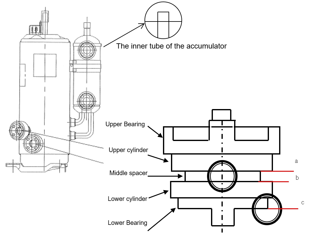
Accumulator liquid level height judgment standard
No exceed the inner tube of the accumulator
Refrigerant does not allow liquid compression
Oil level height judgment standard
| Frequency of operation | Lowest oil level | Transition period |
| 15~30Hz | Line a | - |
| 30~110Hz | Line b | Line c in 3 mins |
The oil level judgment standard is as above, when the working conditions are stable, the minimum oil level corresponding to the operating frequency is as follows:
- Frequency 15-30Hz, the lowest oil level should be above line a ;
- Frequency 30-110Hz, the lowest oil level should be above line b during the stable operation period, and if the oil level fluctuation is below line b during the transition period, the oil level fluctuation should be above line c within 3 minutes, and then stabilize above line b.
Evaluation of experimental conditions
(1) Heating and low-temperature sleep start (placed for 12H)
(2) Heating and low-temperature defrosting
(3) Overload restart
(4) Minimum refrigeration operation
*Ultra-low temperature conditions can be added upon request
Superheat (reference)
△t = compressor cover temperature – the temperature of the saturated liquid in the condenser.
△t value reference: △t ≥ 0°C during transition and △t ≥ 6°C when stable
When the △t value is negative, it will be judged according to the oil level.
Note: There will be different oil-level judgment standards based on various models.
Visualization of oil return evaluation conditions & related requirements
| Experimental project | DBT/WBT (℃) | Outlet water Temp.(℃) | Test Method | |||
| Cooling | 1 | Stated-cooling Restart | 35/-℃ | 7 | After stable operation, stop for 3 minutes → start running Observe the oil level during the whole start-up process (about 10 minutes) | |
| 2 | Max-load Restart | 43/-℃ | 20 | Same as above | ||
| 3 | Min-load Restart | 21/-℃ | 5 | Same as above | ||
| Heating | 4 | Stated-heating Restart | 7/6℃ | 50 | Same as above | |
| 5 | Max-load Restart | 21/15.5℃ | 55 | Same as above | ||
| 6 | Defrosting condition | Sleep Start | 2/1℃ | 12 | The compressor power off, and stand for more than 12 hours → start operation Observe the oil level during the whole start-up process (about 10 minutes) | |
| Defrosting | 55 | Observe the oil level throughout the defrost and start-up process The test process ≥ at least 2 defrost cycles | ||||
| 7 | -5℃ | Defrosting | -5℃/-6℃ | 55 | Observe the oil level throughout the defrost and start-up process The test process ≥ at least 2 defrost cycles | |
| 8 | -12℃ | Sleep Start | -12/-13.5℃ | 12 | The compressor power off, and stand for more than 12 hours → start operation Observe the oil level during the whole start-up process (about 10 minutes) | |
| Defrosting※ | 55 | Observe the oil level throughout the defrost and start-up process The test process ≥ at least 2 defrost cycles | ||||
| 9 | -30℃ | Sleep Start | -30/-℃ | 12 | The compressor power off, and stand for more than 12 hours → start operation Observe the oil level during the whole start-up process (about 10 minutes) | |
| Defrosting※ | 41 | Observe the oil level throughout the defrost and start-up process The test process ≥ at least 2 defrost cycles | ||||
Note: The above experimental items are formulated concerning GB working conditions, and are appropriately adjusted or added according to the customer’s application range/compressor operating range, such as maximum water outlet temperature/minimum water outlet temperature.
※ -12°C / -30°C defrost depends on the customer’s logic, if the customer does not set the defrost condition (time/temperature), then the continuous operation for 3H to observe the oil/liquid level can be.
■Oil level record (focusing on transitional/unsteady phases) :(1) Lowest position of oil level & residence time (2) Highest position of liquid level & residence time
■Superheat (reference)
△t = compressor cover temperature – temperature of the saturated liquid of the condenser;
△t value reference: △t ≥ 0°C during transition, △t ≥ 6°C when stable; When the △t value is negative, it will be judged according to the oil level;